This paper proposes a phased array photodetector chip scheme based on phase difference filtering for grating encoders, aiming to address the bottleneck of traditional grating encoders in balancing precision and miniaturization. The core innovation of the proposed method lies in its optimized signal processing and structural design. The method further subdivides each field in the four-field column method into multiple row combinations with different phases, and weakens high-order harmonic components through the phase arrangement relationship between row combinations, thereby improving the quality of Moiré fringe signals. It meets the demand for a compact array layout while ensuring good photoelectric conversion efficiency. To ensure the scheme’s feasibility and integration, the research adopts a cross-disciplinary integrated approach that combines optics, mechanics, and electronics. It integrates technologies such as phase difference filtering and optoelectronic integration into the development of photodetectors, and designs a dedicated integrated optoelectronic chip based on the developed detector. The research verifies the scheme through a rigorous three-step process: theoretical modeling, structural innovation (to design the folded-line array layout for compactness), and process verification (to ensure compatibility with standard semiconductor manufacturing processes). Simulation results confirm that the developed folded-line array photodetector exhibits excellent orthogonality in photoelectric signal conversion, a key indicator of measurement accuracy. Meanwhile, the chip’s compact array layout reduces its overall volume by approximately 30% compared to traditional discrete detector modules, while maintaining a high photoelectric conversion efficiency of over 85%.
| Published in | International Journal of Sensors and Sensor Networks (Volume 13, Issue 2) |
| DOI | 10.11648/j.ijssn.20251302.15 |
| Page(s) | 65-70 |
| Creative Commons |
This is an Open Access article, distributed under the terms of the Creative Commons Attribution 4.0 International License (http://creativecommons.org/licenses/by/4.0/), which permits unrestricted use, distribution and reproduction in any medium or format, provided the original work is properly cited. |
| Copyright |
Copyright © The Author(s), 2025. Published by Science Publishing Group |
Grating Encoder, Phase Difference Filtering, Moiré Fringe Signal, Photodetector
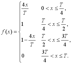 (1)
(1) 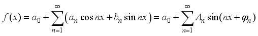 (2)
(2) 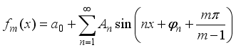 (3)
(3) 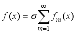 (4)
(4) CNC | Computer Numerical Control |
IDM | The Image-based Displacement Measurement Technology |
DC | Direct Current |
MOS | Metal-oxide Semiconductor |
VPP | Peak-to-Peak Voltage |
X-FAB | Semiconductor Process Name |
| [1] | Luo, L. B., et al. A Review: Grating Encoder Technologies for Multi-Degree-of-Freedom Spatial Measurement. Sensors 2025, 25(19), 6071; |
| [2] | Li, Y. T., et al. Analysis of Photoelectric Detection Phase Polarity of Fiber-Optic Hydrophones Based on 3 × 3 Coupler Demodulation Technique. Photonics 2025, 12(6), 535; |
| [3] | Yang, X. Design of a Reflective Photoelectric Encoder Chip. Master’s Thesis, Tianjin University, Tianjin, China, 2023. |
| [4] | Yao, Z. J., Yao, J. On the Organizational Model of Technological Leapfrogging. Studies in Science of Science, 2004, (02): 144-149. |
| [5] | Li, C. W. Research on Miniaturized High-Precision Absolute Circular Time-Grating Sensor. Master’s Thesis, Chongqing University of Technology, Chongqing, China, 2020. |
| [6] | Ye, S. X. Precision Photoelectric Displacement Measurement Technology. Chengdu: Sichuan Science and Technology Press, 2003. |
| [7] | Zhang, S. C. Metrological Grating Technology. Beijing: China Machine Press, 1985, pp. 8-56. |
| [8] | Wang, F. W. Design of ASIC Chip for High-Precision Photoelectric Encoder and Its Test System. Doctoral Thesis, University of Chinese Academy of Sciences (Changchun Institute of Optics, Fine Mechanics and Physics, Chinese Academy of Sciences), Changchun, China, 2024. |
| [9] | Lin, N., Yang, W. H., Chen, Y. Y., et al. Research Progress and Development Trend of Extreme Ultraviolet Lithography Light Sources. Laser & Optoelectronics Progress, 2022, 59(9): 0922002. |
| [10] | Chen, Y., Sun, C. P., He, H. Y. Research on Encoding Method of Single-Ring Absolute Code Disc. ACTA PHOTONICA SINICA, 2006, 35(3): 460-463. |
| [11] | Wu, H. S., Zeng, Q. F., Qiao, D., et al. Filtering Methods for Improving Signal Quality of Grating Moiré Fringes. Optics and Precision Engineering, 2011, 19(08): 1944-1949. |
| [12] | Zhong, H. R., Liu, T. H., Lu, Q. S., et al. Review on Damage Mechanism of Lasers to Photoelectric Detectors. High Power Laser and Particle Beams, 2000, 12(04): 0. |
| [13] | Khonina, S. N., Kotlyar, V. V., Shinkaryev, M. V., Soifer, V. A., Uspleniev, G. V. The Phase Rotor Filter. Journal of Modern Optics, 1992, 39(5): 1147–1154. |
| [14] | Su, Y. L. A Multiple Pre-Correlation Differential GPS Signal Detection Method. Modern Navigation, 2017, 8(01): 9-13. |
| [15] | Wang, Z. D. Research on Control Technology of Single-Rotor Inverter Compressor Based on Permanent Magnet Synchronous Motor. Master’s Thesis, South China University of Technology, Guangzhou, China, 2017. |
| [16] | Huang, M. Research on Self-Calibration Method of Stitched Linear Time-Grating Displacement Sensor. Master’s Thesis, Chongqing University of Technology, Chongqing, China, 2024. |
| [17] | Zhang, S. Z., Pu, Z. B. Evaluation of Grating Signal Quality and Determination of Grating System Parameters. Journal of Astronautic Metrology and Measurement, 1983, (06): 1-6+75. |
| [18] | Zhang, G. J. Visual Measurement. Beijing: Science Press, 2008. |
| [19] | Ma, L., Yan, M. J., Guo, C. Y., et al. Experimental Research Progress of Continuous-Variable High-Order Mode Squeezed Light Fields. Laser & Optoelectronics Progress, 2022, 59(1): 0100005. |
| [20] | Dew, G. D. On Preparing Plastic Copies of Diffraction Gratings; an Extension to the Merton-NPL Process. Journal of Scientific Instruments, 1956, 33(9): 348. |
| [21] | Mu, Y. S. Research on ASIC Photoelectric Chip for High-Precision Angular Displacement Sensor. Master’s Thesis, Jilin University, Changchun, China, 2020. |
| [22] | Chen, Y., Chen, H. B., Sun, G. Q., et al. Improvement of Signal Quality of Grating Moiré Fringes and Its Acquisition Method. Journal of Shanghai University (Natural Science Edition), 2004, (02): 129-132. |
APA Style
Wang, Z., Zhao, Z., Mu, Y. (2025). Development of a Specialized Phased Array Photodetector Chip for Grating Encoders Using Phase Difference Filtering. International Journal of Sensors and Sensor Networks, 13(2), 65-70. https://doi.org/10.11648/j.ijssn.20251302.15
ACS Style
Wang, Z.; Zhao, Z.; Mu, Y. Development of a Specialized Phased Array Photodetector Chip for Grating Encoders Using Phase Difference Filtering. Int. J. Sens. Sens. Netw. 2025, 13(2), 65-70. doi: 10.11648/j.ijssn.20251302.15
AMA Style
Wang Z, Zhao Z, Mu Y. Development of a Specialized Phased Array Photodetector Chip for Grating Encoders Using Phase Difference Filtering. Int J Sens Sens Netw. 2025;13(2):65-70. doi: 10.11648/j.ijssn.20251302.15
@article{10.11648/j.ijssn.20251302.15,
  author = {Ziyu Wang and Zilong Zhao and Yusong Mu},
  title = {Development of a Specialized Phased Array Photodetector Chip for Grating Encoders Using Phase Difference Filtering
},
  journal = {International Journal of Sensors and Sensor Networks},
  volume = {13},
  number = {2},
  pages = {65-70},
  doi = {10.11648/j.ijssn.20251302.15},
  url = {https://doi.org/10.11648/j.ijssn.20251302.15},
  eprint = {https://article.sciencepublishinggroup.com/pdf/10.11648.j.ijssn.20251302.15},
  abstract = {This paper proposes a phased array photodetector chip scheme based on phase difference filtering for grating encoders, aiming to address the bottleneck of traditional grating encoders in balancing precision and miniaturization. The core innovation of the proposed method lies in its optimized signal processing and structural design. The method further subdivides each field in the four-field column method into multiple row combinations with different phases, and weakens high-order harmonic components through the phase arrangement relationship between row combinations, thereby improving the quality of Moiré fringe signals. It meets the demand for a compact array layout while ensuring good photoelectric conversion efficiency. To ensure the scheme’s feasibility and integration, the research adopts a cross-disciplinary integrated approach that combines optics, mechanics, and electronics. It integrates technologies such as phase difference filtering and optoelectronic integration into the development of photodetectors, and designs a dedicated integrated optoelectronic chip based on the developed detector. The research verifies the scheme through a rigorous three-step process: theoretical modeling, structural innovation (to design the folded-line array layout for compactness), and process verification (to ensure compatibility with standard semiconductor manufacturing processes). Simulation results confirm that the developed folded-line array photodetector exhibits excellent orthogonality in photoelectric signal conversion, a key indicator of measurement accuracy. Meanwhile, the chip’s compact array layout reduces its overall volume by approximately 30% compared to traditional discrete detector modules, while maintaining a high photoelectric conversion efficiency of over 85%.
},
 year = {2025}
}
TY  - JOUR
T1  - Development of a Specialized Phased Array Photodetector Chip for Grating Encoders Using Phase Difference Filtering

AU  - Ziyu Wang
AU  - Zilong Zhao
AU  - Yusong Mu
Y1  - 2025/11/26
PY  - 2025
N1  - https://doi.org/10.11648/j.ijssn.20251302.15
DO  - 10.11648/j.ijssn.20251302.15
T2  - International Journal of Sensors and Sensor Networks
JF  - International Journal of Sensors and Sensor Networks
JO  - International Journal of Sensors and Sensor Networks
SP  - 65
EP  - 70
PB  - Science Publishing Group
SN  - 2329-1788
UR  - https://doi.org/10.11648/j.ijssn.20251302.15
AB  - This paper proposes a phased array photodetector chip scheme based on phase difference filtering for grating encoders, aiming to address the bottleneck of traditional grating encoders in balancing precision and miniaturization. The core innovation of the proposed method lies in its optimized signal processing and structural design. The method further subdivides each field in the four-field column method into multiple row combinations with different phases, and weakens high-order harmonic components through the phase arrangement relationship between row combinations, thereby improving the quality of Moiré fringe signals. It meets the demand for a compact array layout while ensuring good photoelectric conversion efficiency. To ensure the scheme’s feasibility and integration, the research adopts a cross-disciplinary integrated approach that combines optics, mechanics, and electronics. It integrates technologies such as phase difference filtering and optoelectronic integration into the development of photodetectors, and designs a dedicated integrated optoelectronic chip based on the developed detector. The research verifies the scheme through a rigorous three-step process: theoretical modeling, structural innovation (to design the folded-line array layout for compactness), and process verification (to ensure compatibility with standard semiconductor manufacturing processes). Simulation results confirm that the developed folded-line array photodetector exhibits excellent orthogonality in photoelectric signal conversion, a key indicator of measurement accuracy. Meanwhile, the chip’s compact array layout reduces its overall volume by approximately 30% compared to traditional discrete detector modules, while maintaining a high photoelectric conversion efficiency of over 85%.

VL  - 13
IS  - 2
ER  -
School of Electrical and Computer Engineering, Jilin Jianzhu University, Changchun, China
School of Electrical and Computer Engineering, Jilin Jianzhu University, Changchun, China
Modern Industry College, Jilin Jianzhu University, Changchun, China
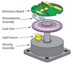
Figure 1. Schematic Diagram of Grating Encoder Structure.
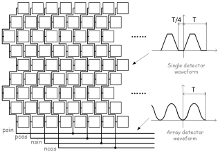
Figure 2. Filtering Principle of Phase Difference Detector Array.
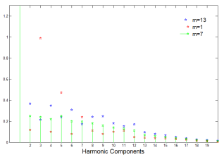
Figure 3. Analysis of the Influence of the Number of Detectors on Harmonic Components.
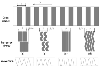
Figure 4. Simulation Analysis of Detector Array.
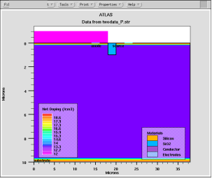
Figure 5. Simulation Results of Photoelectric Detector.
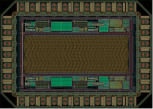
Figure 6. Layout of Folded-Line Phase Array Detector.
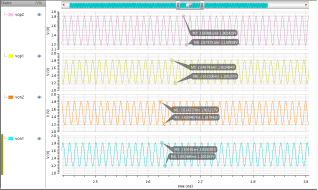
Figure 7. Transient Simulation Results of Chip Layout.